Monday, December 21, 2015

Printing Address Labels from Spreadsheet Data Source with LibreOffice (OpenOffice)

Every year it takes me a solid hour to figure out how to run a mail merge using LibreOffice so that I can print labels for my Christmas cards.

It really isn't that difficult, but I documented the process here for myself and hopefully others:

Before starting, all of your addresses should be in a spreadsheet, with each column representing a unique bit of information.  What I'm doing is:
  • Addresses are stored in a Google Docs spreadsheet which both my wife and I have access to 
  • I want to use LibreOffice to print labels using this spreadsheet as a source
To start, I export the Google Docs spreadsheet to LibreOffice format.  Now:

1.  Start LibreOffice Base (if you don't have Base, you may need to install it:  sudo apt-get install libreoffice-base)

2.  Create a new database from spreadsheet.
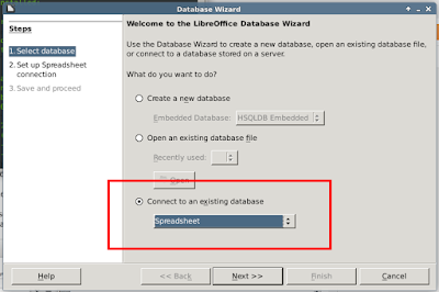


3.  Point to the spreadsheet that contains your addresses.
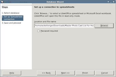


4.  Allow Base to register the database for you, because you will need to see it from the word processor.
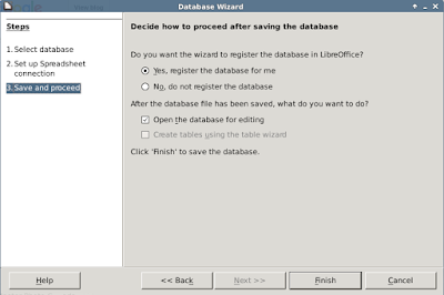


5.  Click 'Finish' and save the database.

6.  Open LibreOffice Writer

7.  Select File --> New --> Labels


8.  In the resulting dialog, see below for detailed explanation:


A.  Select the brand and type of labels you want to print.
B.  Select the database you created earlier.
C.  Select the table the data will come from (if you started with a spreadsheet there should probably only be one table here)
D.  Select the field to add to the label
E.  Add the field into the label
F.  Repeat D and E, and arrange the fields in the "Label Text" box.
G. Finally make sure the correct printer is selected under the "Options" tab.

Note for section F I have arranged fields like so:
[First Name] [Last Name]
[Address]
[City], [State]  [Zip]


9.  Go to the options tab.  This is critical.
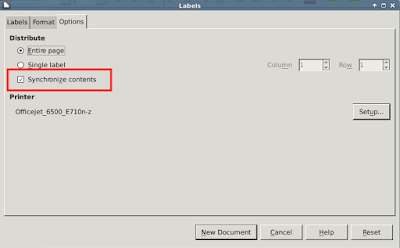


Select "Synchronize contents" and set up your printer.  The "Synchronize contents" option will allow you to manipulate the formatting of the first label, and apply those changes to all of the labels.

Click 'New Document' when you're finished.

10.  Done.
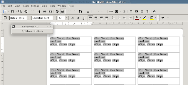


11.  Now, we probably want to clean things up a bit.  I like to center the address horizontally and vertically, and maybe change the font.  Do this for the first label:
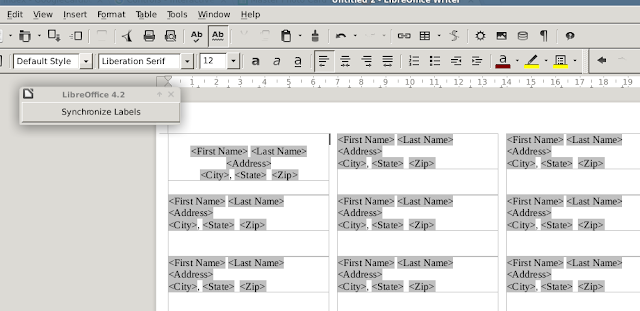


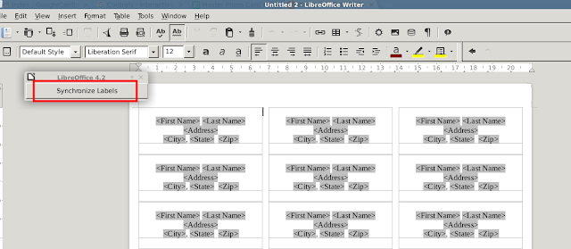
12.  Once you've made your changes to the first label, click "Synchronize Labels" to apply the changes to all labels.


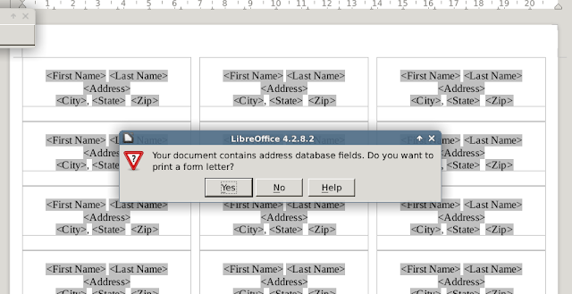
13.  When you're done formatting, do File --> Print.  You will get this message, to which you will click "Yes" to continue.


14.  After clicking "Yes" you are presented with yet another dialog:
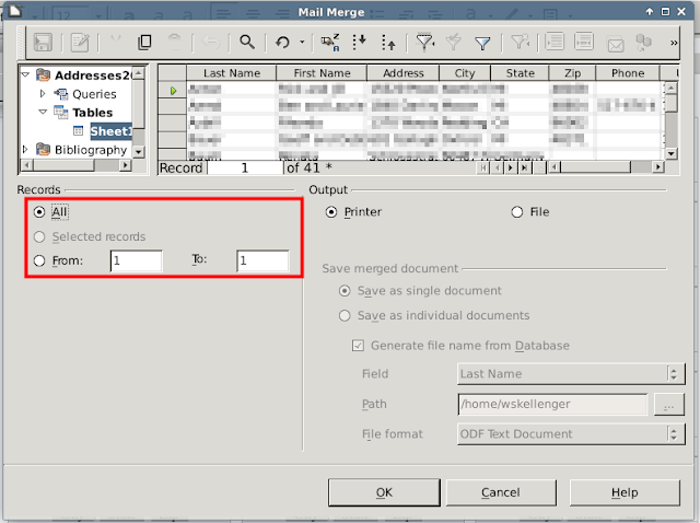


For the final project, you probably want to select "All" to merge all, but for a test, maybe try merging the first 10 records or so and printing.

When you have maybe addresses printed on plain paper, you can hold the plain paper over the labels, then hold them both up to bright light to see if the labels would align properly.

When you are satisfied, load labels and print.


Monday, April 13, 2015

Installing kanboard onto a Raspberry Pi

I wanted to try running the open source software "kanboard" on my Raspberry Pi.  The installation was pretty simple.

First, get updates.

sudo apt-get update

Now install the web server, Apache:

sudo apt-get install apache2

After this is finished, you should try to hit your Raspberry Pi with your browser (type in the address of your Pi and hit enter):


We also need php.


sudo apt-get install php5

sudo apt-get install php php-gd php-mbstring php-dom


And we need the sqlite plugin as well as unzip if you don't have it already:

sudo apt-get install unzip php5-sqlite
sudo apt-get install unzip php7.0-sqlite3


Now restart the webserver:

sudo service apache2 restart

And do:

   sudo su
   cd /var/www/html
   git clone https://github.com/kanboard/kanboard.git
   cd kanboard && git checkout v1.2.5 && cd ..
   chown -R www-data:www-data kanboard/data
   service apache2 restart

Now try to hit http://<your pi IP address>/html/kanboard from your browser, if you were successful you should see:


Tuesday, March 31, 2015

Amazon Dash?

This caught me off guard today: a free Dash button (for Prime members only) to instantly purchase certain products from Amazon:


Amazon has posted a YouTube video demonstrating the use of the button.

My first reaction: how long will it take for the maker/hacker community to figure out other uses for this button?

My second reaction after watching the video:  I could use this.

So I requested an invite.


Amazon is also pretty, um, curt with their terms and conditions:


I'm very curious how it works.  There is some indication that using an app on your phone is how you configure what product the button is tied to:


There is no indication as to how the button press translates into the order, but using the Google patent search I found this little gem, which describes using SMS messaging to complete "one click" orders.  I'm guessing that's what we have here, a tiny cell transmitter, very difficult to modify and use for other purposes.

We'll see...


Scanning Double-Sided Documents With a Single Sheet Scanner Under Linux

I like to keep documents.  Receipts, statements, manuals, pamphlets, you name it.  I file things away in hanging folders for later reference.

Since the kiddos came along it has gotten harder and harder to make time for all of this organization, and with a huge pile of unfiled documents I knew I had to find a way to make this easier, or least require less space.

Digitizing the documents seemed like a great answer.  I got an OfficeJet 6500A about a year ago, and I've created a couple of scripts to make scanning a little easier on the Linux desktop.

I've broken down document scanning into a few separate tasks, most of these tasks were scripted:

  1. Scan physical documents into TIFF format
  2. Compress/convert TIFF files into JPEG files to reduce space
  3. Convert JPEG files into PDF (mainly for portability)
  4. Create double-sided PDF documents (so that the front side and back side of a single page are in one PDF file)
  5. Concatenate the double-sided PDF files into a single PDF file.

Prerequisites for Linux:

  • convert (package: imagemagick).  The ImageMagick package provides a commandline tool called 'convert' that will handle image conversion.
  • scanimage (package: sane (or sometimes sane-utils)).  This will actually handle the scanning.
  • pdftk (package: pdftk).  The pdf toolkit will handle just about any PDF-related digital activity you can think of.
  • (In Ubuntu/Mint:  sudo apt-get install imagemagick sane pdftk)

Setup

In my case I'm using an HP Officejet 6500A Plus.  Make sure you've set up the printer with hp-setup and that you can print to it from other applications.

Test your setup by typing "scanimage" at the commandline and see what happens.  You should see something like:

scanimage: output is not a file, exiting

If you don't have any error messages, you can skip past the following troubleshooting steps.

Troubleshooting

Potential problem 1:

wskellenger@marquette ~ $ scanimage
scanimage: no SANE devices found

Solution:

uncomment hpaio in /etc/sane.d/dll.conf

...snip from dll.conf...

#umax_pp
umax1220u
#v4l    #don't care about this
hpaio   #uncomment this line

Potential problem 2:

Note the very last line, which contains the error:

wskellenger@marquette ~ $ scanimage
MIB search path: /home/wskellenger/.snmp/mibs:/usr/share/snmp/mibs:/usr/share/snmp/mibs/iana:/usr/share/snmp/mibs/ietf:/usr/share/mibs/site:/usr/share/snmp/mibs:/usr/share/mibs/iana:/usr/share/mibs/ietf:/usr/share/mibs/netsnmp
Cannot find module (SNMPv2-TC): At line 10 in /usr/share/snmp/mibs/UCD-DLMOD-MIB.txt
Cannot find module (SNMPv2-SMI): At line 34 in /usr/share/snmp/mibs/UCD-SNMP-MIB.txt
Cannot find module (SNMPv2-TC): At line 37 in /usr/share/snmp/mibs/UCD-SNMP-MIB.txt
Did not find 'enterprises' in module #-1 (/usr/share/snmp/mibs/UCD-SNMP-MIB.txt)
Did not find 'DisplayString' in module #-1 (/usr/share/snmp/mibs/UCD-SNMP-MIB.txt)
Did not find 'TruthValue' in module #-1 (/usr/share/snmp/mibs/UCD-SNMP-MIB.txt)
Unlinked OID in UCD-SNMP-MIB: ucdavis ::= { enterprises 2021 }
Undefined identifier: enterprises near line 39 of /usr/share/snmp/mibs/UCD-SNMP-MIB.txt
Did not find 'DisplayString' in module #-1 (/usr/share/snmp/mibs/UCD-DLMOD-MIB.txt)
Did not find 'ucdExperimental' in module UCD-SNMP-MIB (/usr/share/snmp/mibs/UCD-DLMOD-

..... stuff removed .....

Cannot adopt OID in UCD-SNMP-MIB: dskUsed ::= { dskEntry 8 }
Cannot adopt OID in UCD-SNMP-MIB: dskAvail ::= { dskEntry 7 }
Cannot adopt OID in UCD-SNMP-MIB: dskTotal ::= { dskEntry 6 }
Cannot adopt OID in UCD-SNMP-MIB: dskMinPercent ::= { dskEntry 5 }
Cannot adopt OID in UCD-SNMP-MIB: dskMinimum ::= { dskEntry 4 }
Cannot adopt OID in UCD-SNMP-MIB: dskDevice ::= { dskEntry 3 }
Cannot adopt OID in UCD-SNMP-MIB: dskPath ::= { dskEntry 2 }
Cannot adopt OID in UCD-SNMP-MIB: dskIndex ::= { dskEntry 1 }
Cannot adopt OID in UCD-DISKIO-MIB: diskIOTable ::= { ucdDiskIOMIB 1 }
Cannot adopt OID in NET-SNMP-AGENT-MIB: nsLoggingGroup ::= { nsConfigGroups 2 }
Cannot adopt OID in NET-SNMP-AGENT-MIB: nsDebugGroup ::= { nsConfigGroups 1 }
Cannot adopt OID in UCD-SNMP-MIB: snmperrErrMessage ::= { snmperrs 101 }
Cannot adopt OID in UCD-SNMP-MIB: snmperrErrorFlag ::= { snmperrs 100 }
Cannot adopt OID in UCD-SNMP-MIB: snmperrNames ::= { snmperrs 2 }
Cannot adopt OID in UCD-SNMP-MIB: snmperrIndex ::= { snmperrs 1 }
Cannot adopt OID in NET-SNMP-AGENT-MIB: nsTransactionTable ::= { nsTransactions 1 }
Cannot adopt OID in NET-SNMP-AGENT-MIB: nsLogStatus ::= { nsLoggingEntry 5 }
Cannot adopt OID in NET-SNMP-AGENT-MIB: nsLogMaxLevel ::= { nsLoggingEntry 4 }
Cannot adopt OID in NET-SNMP-AGENT-MIB: nsLogType ::= { nsLoggingEntry 3 }
Cannot adopt OID in NET-SNMP-AGENT-MIB: nsLogToken ::= { nsLoggingEntry 2 }
Cannot adopt OID in NET-SNMP-AGENT-MIB: nsLogLevel ::= { nsLoggingEntry 1 }
Cannot adopt OID in NET-SNMP-EXTEND-MIB: nsExtendResult ::= { nsExtendOutput1Entry 4 }
Cannot adopt OID in NET-SNMP-EXTEND-MIB: nsExtendOutNumLines ::= { nsExtendOutput1Entry 3 }
Cannot adopt OID in NET-SNMP-EXTEND-MIB: nsExtendOutputFull ::= { nsExtendOutput1Entry 2 }
Cannot adopt OID in NET-SNMP-EXTEND-MIB: nsExtendOutput1Line ::= { nsExtendOutput1Entry 1 }
Cannot adopt OID in NET-SNMP-EXTEND-MIB: nsExtendOutLine ::= { nsExtendOutput2Entry 2 }
Cannot adopt OID in NET-SNMP-EXTEND-MIB: nsExtendLineIndex ::= { nsExtendOutput2Entry 1 }
Cannot adopt OID in NET-SNMP-AGENT-MIB: nsNotifyStart ::= { netSnmpNotifications 1 }
Cannot adopt OID in NET-SNMP-AGENT-MIB: nsNotifyShutdown ::= { netSnmpNotifications 2 }
Cannot adopt OID in NET-SNMP-AGENT-MIB: nsNotifyRestart ::= { netSnmpNotifications 3 }
Cannot adopt OID in UCD-SNMP-MIB: laErrMessage ::= { laEntry 101 }
Cannot adopt OID in UCD-SNMP-MIB: laErrorFlag ::= { laEntry 100 }
Cannot adopt OID in UCD-SNMP-MIB: laLoadFloat ::= { laEntry 6 }
Cannot adopt OID in UCD-SNMP-MIB: laLoadInt ::= { laEntry 5 }
Cannot adopt OID in UCD-SNMP-MIB: laConfig ::= { laEntry 4 }
Cannot adopt OID in UCD-SNMP-MIB: laLoad ::= { laEntry 3 }
Cannot adopt OID in UCD-SNMP-MIB: laNames ::= { laEntry 2 }
Cannot adopt OID in UCD-SNMP-MIB: laIndex ::= { laEntry 1 }
scanimage: open of device hpaio:/net/Officejet_6500_E710n-z?ip=192.168.1.125 failed: Error during device I/O

Solution:


I had this issue when my wireless printer was set to get an IP Address automatically using DHCP. You might see this in the HP Device Manager -- an indication that all is not well communicating with the printer:


Do the following:
  • Drop the printer from the HP Device Manager or from CUPS
  • Configure the printer for a static IP address
  • Add the printer to HP Device Manager or CUPS again
This is what you should see -- an indication that all is well:


When you run scanimage now, you may still get a bunch of "Cannot adopt OID" warnings, but it should still work and hopefully you can make a scan from the commandline.  You should *not* get the "Error during device I/O" message that is highlighted above.


You need to have "scanimage" working at this point to continue.

Let's scan some stuff.

Installing the Scripts

You can get the scripts from my git repo here. Note, you need Python 2.x to run them. Clone the repo and then find your file manager below:
  • Nautilus: Use the master branch of the scripts and copy everything into your ~/.gnome2/nautilus-scripts/ directory. 
  • Thunar: Use the master branch of the scripts. I'm pretty sure you have to edit the "Custom Actions" in the Edit menu and add each script manually. I tested it and it worked, but it was in Arch Linux and I've since gone back to Mint. So I don't have screenshots of that configuration but it wasn't too difficult. 
  • Nemo: Use the nemo branch of the repo and copy everything into your ~/.gnome2/nemo-scripts/  /.local/share/nemo/scripts
  • Other: ??? The scripts are pretty generic, they should work with almost any extendable file manager. 
  • In order for pdf conversions to work properly in newer (2018+) versions of convert, you need to change the policy file in /etc/ImageMagick-6/policy.xml.  See here.

Workflow


  1. This example uses four double-sided pages 
  2. Pages are numbered (front/back) 1/2, 3/4, 5/6, 7/8. 
  3. Load the documents into the scanner in order, with page one facing up (page one will be scanned first), and run the script "Scan sheet feeder documents to PDF" 
  4. The documents will now be face down, with the last page (8) at the top. Grab the stack of documents as is, rotate 180 degrees, and put into the sheet feeder again. 
  5. The sheets are loaded exactly as they came out of the scanner, the back of the last page should be at the top, facing up. Run the script "Scan sheet feeder documents to PDF" again. 
  6. The sheets are now in the original order. You are done handing the paper. 

Postprocessing

Now we need to duplex the output (put the fronts and backs together) and concatenate the resulting documents (put them together).

Duplex the front and back pages of the output:

Select all of the pages you scanned and create duplex PDFs (this will put together pages 1+2, 3+4, 5+6, 7+8)

Finally, concatenate the duplexed pages into complete documents, as desired:

Select some or all of the above duplexed documents and concatenate into single documents as necessary.

If you're confused, watch this:


Why so many steps?

One of the goals was to be able to take a huge stack of receipts, statements, whatever documents, and scan them all at once. When finished there is some tedious renaming, but for me this is easier than manual filing in a file cabinet.

Notes:
  • If you only scan a bunch of single-sided documents, you can skip the duplex step and just concatenate all of the pages immediately, or do nothing and you have a bunch of single sided scans.
  • If you have a bunch of mismatched documents, as I described, you can select three or four of your duplexed documents, and concatenate only those if you wish. 

Scan some stuff

In Nautilus (or Nemo or Thunar), navigate to the folder where you want the scans to go.  From here right click and select Scripts --> 1-Scan_sheet_feeder_docs_to_PDF.  It may take a few seconds, but your scanner should fire up and start scanning.  The files will first be scanned to .tiff, then compressed to .jpg, then converted to .pdf.  I took the extra step of .jpg compression to reduce the file size before converting to .pdf.  The .tiff may be 24 MB in size while a .jpg of the same file might only be 600 kb.  The extra step is worth it.

Once the files are scanned, you'll have a bunch of files the destination directory like so:

scan1409007022-1.pdf
scan1409007022-2.pdf
scan1409007022-3.pdf
scan1409007022-4.pdf
scan1409007022-5.pdf
scan1409007022-6.pdf
scan1409007851-1.pdf
scan1409007851-2.pdf
scan1409007851-3.pdf
scan1409007851-4.pdf
scan1409007851-5.pdf
scan1409007851-6.pdf

The naming convention is scan(start_time)-(number).pdf.

The first six scans are all of the front sides of the pages, the second six scans are the back sides.

The front side files are all numbered scan1409007022 while the back side files are all numbered scan1409007851.

When you scan all of the front sides first, and then flip the stack over, and scan the back sides, the files need to be duplexed in a special sequence, that is (don't worry, I handle this automatically!):
  • front side file #1 + back side file #6
  • front side file #2 + back side file #5
  • front side file #3 + back side file #4
  • front side file #4 + back side file #3
  • front side file #5 + back side file #2
  • front side file #6 + back side file #1
Now we just need to select all of the files you just scanned, and then right click, and select scripts --> 2-Make_Duplex_PDFs.  The script will combine the files as described above.

Now you've got:

dplx-scan1409007022-01-06.pdf
dplx-scan1409007022-02-05.pdf
dplx-scan1409007022-03-04.pdf
dplx-scan1409007022-04-03.pdf
dplx-scan1409007022-05-02.pdf
dplx-scan1409007022-06-01.pdf

We're almost done!

At this point, if the stack of papers you scanned are all from the same document, just select them all, right click, and select 3-Concatenate_Selected_PDFs.  The script will ask you if you want to rename the result, and then it will ask you if it should delete the files you've selected.

If the stack of papers you scanned are from DIFFERENT documents, you can select the group of duplexed documents that represent one document, and then concatenate those.  Repeat until you've concatenated the files into the appropriate document.

For example:

dplx-scan1409007022-01-06.pdf
dplx-scan1409007022-02-05.pdf
dplx-scan1409007022-03-04.pdf

might be a T-Mobile bill, while:

dplx-scan1409007022-04-03.pdf
dplx-scan1409007022-05-02.pdf

...is a bank statement and:

dplx-scan1409007022-06-01.pdf

...is a cable bill.

You proceed as above, select the documents that belong together, and then right click, select scripts, then 3-Concatenate_Selected_PDFs.

And that's it.

I've added some additional scripts that I find useful:

4-Rotate_Selected_PDFs
5-Scan_flatbed_docs_to_PDF
6-Scan_flatbed_photo_to_JPG

They pretty much do what they say.


Thursday, March 26, 2015

Set your Raspberry Pi shell prompt to another color

I've got two terminal windows open, one is on my local machine and the other is on my Raspberry Pi.  The problem I've got is that when I'm switching back and forth I sometimes forget if I'm in the correct window or not.  Here is what they look like:


They look exactly the same, save for the "pi@raspberrypi" prompt in one window vs. the other.

I want the Rpi to have a pink or red or raspberry (heh) or some other bright colored prompt.

Alter .bashrc with whatever editor you want.  I use vim, so from your home directory:

vim .bashrc

Look for these lines:


I want something sort of startling -- so I know I'm at the rpi prompt.

You can find a list of color codes here.

Here's what I changed:


Then do a "source .bashrc" when you're finished.


Pretty simple.  I'm not sure if I'm startled enough by it -- but it is a good start.


Sunday, March 15, 2015

Programming an ATmega (168, 328) using your Arduino as a programmer

You might be working on a project with your Arduino, and you've decided that it is time to move your project OFF of the Arduino board.  There are a lot of reasons for doing so:
  • Make your project smaller
  • Eliminate the stuff you don't need (voltage regulator, USB to serial converter, etc)
  • Consume less power by not having the extra stuff
  • Reduce cost
Before continuing you should know these definitions:

ATmega168, ATmega328:  An 8-bit microcontroller made by Atmel.  This is a "chip" with some pins on it, it fits in the palm of your hand.  
Arduino:  A circuit board for hobbyists, usually containing an ATmega168/328.  It has an onboard voltage regulator, USB port, header pins, LEDs, and protection circuitry.  

When I mention the "Arduino" I want to be clear that I am talking about the development board, not the microcontroller that is on it.  I will try to use "ATmegaxxx" when I am talking about the microcontroller IC.

Turn your Arduino into an In-System Programmer (ISP)

I had an ATmega168 in a drawer and I wanted to use it on a breadboard without the Arduino.  I needed to know also how to program the device without a programmer.

Well, included with the Arduino IDE is a sketch under examples called ArduinoISP:


Stop and just FORGET ABOUT the breadboard for a second!  Some other tutorials and having you change the board type and so forth right now.  NO.

Upload the ArduinoISP sketch to your Arduino board as you would any other sketch.

Did it upload successfully?  If so, your Arduino is now a programmer.

Thank you to Randall Bohn for writing the ArduinoISP sketch, this is really pretty amazing.

Some more info can be learned from the comments in the first few lines of the sketch:
// ArduinoISP version 04m3
// Copyright (c) 2008-2011 Randall Bohn
// If you require a license, see 
//     http://www.opensource.org/licenses/bsd-license.php
//
// This sketch turns the Arduino into a AVRISP
// using the following arduino pins:
//
// pin name:    not-mega:         mega(1280 and 2560)
// slave reset: 10:               53 
// MOSI:        11:               51 
// MISO:        12:               50 
// SCK:         13:               52 
//
// Put an LED (with resistor) on the following pins:
// 9: Heartbeat   - shows the programmer is running
// 8: Error       - Lights up if something goes wrong (use red if that makes sense)
// 7: Programming - In communication with the slave

Getting ready to burn the bootloader


At this point we are ready to flash an ATmega168 or 328 IC, using our Arduino board as a programmer.

Wait, why do we need to burn a bootloader anyway?

The bootloader is just a small piece of code on the micro that sets up the execution environment in which your programs (sketches) will run.  Most of the Arduino boards come with the ATmega chip already on it, and it thus already has a bootloader that, among other things, tells it to expect a 16 MHz oscillator.  So if the chip you want to use on a breadboard has already been in an Arduino, it almost certainly is configured this way.  This is important to know going forward.

The Arduino webpage gives some more details about connections, one method includes a crystal (external oscillator) and some capacitors (on the right below), while the other doesn't (on the left below).


Let's stop and take a breather before we panic about not having a 16 MHz crystal and some tiny caps in our junk drawers.

IF the chip you want to use ALREADY HAS a bootloader on it, chances are quite good that it requires the external oscillator, as I mentioned a few paragraphs earlier.  You won't know until you actually try to burn the bootloader and get a message like this in the Arduino IDE:
avrdude: Yikes!  Invalid device signature.
        Double check connections and try again, or use -F to override
        this check.

Optionally, you can confirm what the Arduino IDE is telling you with avrdude from the Linux command line:
wskellenger@marquette ~ $ avrdude -p m168 -P /dev/ttyUSB0 -c avrisp -b 19200

avrdude: AVR device initialized and ready to accept instructions

Reading | ################################################## | 100% 0.05s

avrdude: Device signature = 0x000000 (retrying)

Reading | ################################################## | 100% 0.05s

avrdude: Device signature = 0x000000 (retrying)

Reading | ################################################## | 100% 0.05s

avrdude: Device signature = 0x000000
avrdude: Yikes!  Invalid device signature.
         Double check connections and try again, or use -F to override
         this check.

In this case you *must* use the design on the right, OR, follow this great tip from from the comments here:

If you don't have any crystal, this is a workaround you can use:
1- Before to start the burn the bootloader, connect a jumper wire between the physical pin 9 (XTAL1) of your ATMEGA in the Arduino UNO board and the same pin 9 on the ATMEGA in the breadboard. This will feed temporarily to your standalone chip with a clock signal.

2- Burn the bootloader from the Arduino IDE menu.

3- Disconect the temporary jumper wire, and thats it. Now you can upload the sketches as usual with your Arduino UNO as an ISP.

It also helps to have a sticker on your ATmega chip so you know which pins are where.  I used one from here and some double-sided tape to affix it to the top of my ATmega168.  Note the little half-circle at one end needs to be aligned over the similar shape on the chip itself.  This will help greatly when you are breadboarding with this guy.

With the connections made between your breadboard and the Arduino, you can probe the XTAL1 or XTAL2 pins with a scope (marked XT1 and XT2 on the sticker above), and you should see a nice 16 MHz sine wave already.  If you don't have a scope, assume that signal is there, because if your Arduino is working, it is.

(Here is what avrdude says when I have XTAL1 jumped as described...)
wskellenger@marquette ~ $ avrdude -p m168 -P /dev/ttyUSB0 -c avrisp -b 19200

avrdude: AVR device initialized and ready to accept instructions

Reading | ################################################## | 100% 0.07s

avrdude: Device signature = 0x1e9406

avrdude: safemode: Fuses OK (H:00, E:DD, L:FF)

avrdude done.  Thank you.

Burning the bootloader

  • Okay, we've got the ArduinoISP sketch uploaded onto our Arduino board.
  • We have the appropriate connects made between the Arduino and our breadboard.
  • Our ATmega chip is installed on the breadboard.
  • The Arduino is plugged into our PC and we are ready to burn the bootloader.

Select what type of chip you are going to burn first (If you don't see these options, scroll to the bottom of this post).


Make sure you've selected "Arduino as ISP":


Now select "Burn Bootloader":


Hopefully you see this:


If not:

  • you haven't made the correct connections 
  • possibly you need a 10 uF cap across reset and ground (Arduino Uno)
  • there is a change you need to make to the ArduinoISP sketch (Arduino v1.0)
  • you don't have the external oscillator, so you need to add it or jump from XTAL1 on the Arduino to XTAL1 on the target ATmega IC on the breadboard, as described above.
See these notes from here under "Instructions":


Now what?

Okay, now you have an ATMega168 or 328 on a breadboard.  You've cut the apron strings.  Now in order to flash it, you can still use your Arduino board, but you need to remove the ATmega IC from the Arduino board in order to use it as a programmer to flash sketches onto the breadboarded microcontroller.

Flashing sketches onto the breadboarded ATmega IC:

Adding the "ATmegaxxx on Breadboard" options to the Arduino IDE:

It looks like there are two ways to do this.

Method 1:
In your sketchbook folder, add a folder called "hardware" and unzip this file (Arduino IDE 1.5) or this file (Arduino IDE 1.0) into it.  Reload the IDE, and open the sketch you were working on, and the additional option will be there.  This is discussed under "Minimal Circuit" here.

Method 2:
Modify boards.txt in /usr/share/arduino/hardware/arduino (Linux location):

Here is the text I've added to the end of boards.txt:
##############################################################

atmega328bb.name=ATmega328 on a breadboard (8 MHz internal clock)

atmega328bb.upload.protocol=stk500
atmega328bb.upload.maximum_size=30720
atmega328bb.upload.speed=57600

atmega328bb.bootloader.low_fuses=0xE2
atmega328bb.bootloader.high_fuses=0xDA
atmega328bb.bootloader.extended_fuses=0x05
atmega328bb.bootloader.path=arduino:atmega
atmega328bb.bootloader.file=ATmegaBOOT_168_atmega328_pro_8MHz.hex
atmega328bb.bootloader.unlock_bits=0x3F
atmega328bb.bootloader.lock_bits=0x0F

atmega328bb.build.mcu=atmega328p
atmega328bb.build.f_cpu=8000000L
atmega328bb.build.core=arduino:arduino
atmega328bb.build.variant=standard

##############################################################

atmega168bb.name=ATmega168 on a breadboard (8 MHz internal clock)

atmega168bb.upload.protocol=stk500
atmega168bb.upload.maximum_size=14336
atmega168bb.upload.speed=19200

atmega168bb.bootloader.low_fuses=0xE2
atmega168bb.bootloader.high_fuses=0xDD
atmega168bb.bootloader.extended_fuses=0x00
atmega168bb.bootloader.path=arduino:atmega
atmega168bb.bootloader.file=ATmegaBOOT_168_pro_8MHz.hex

atmega168bb.bootloader.unlock_bits=0x3F
atmega168bb.bootloader.lock_bits=0x0F

atmega168bb.build.mcu=atmega168
atmega168bb.build.f_cpu=8000000L
atmega168bb.build.core=arduino:arduino
atmega168bb.build.variant=standard

Saturday, February 21, 2015

Dealing with Android MTP devices in Linux

A couple of frustrating errors you might see when trying to exchange files with your Android phone:

"-1: Unspecified error."


My personal favorite when copying a file to or from the device, the "-6: Not Supported."


Try using jmtpfs.  From Ubuntu/Mint, it is a simple install with "sudo apt-get install jmtpfs".

It isn't perfect, but better than the "native" MTP transfer provided by libmtp, which is clearly broken in Linux and has been for some time. There is no other explanation, as there are several other MTP solutions which according to the Arch Wiki, "...aim at better functionality and performance over libmtp."

Using jmtpfs is pretty simple, just create a directory to use as a mount point, then use jmtpfs to mount your device at that directory.  You can then use the command line or a file manager to navigate to that folder and copy files to/from it.

Other usage patterns can be found in the jmtpfs readme.

I still got an error while trying to overwrite an existing file, so as I said this solution isn't perfect, but it works better than libmtp with my Moto G.  Here is an example of mounting the device to a directory called "mnt":

Removed demonstration gist, but you can view it here if you are interested.

Update 28-Feb-2015:
After more use, I found that jmtpfs is useful for one or two files, but if you need to transfer, say, all of your phone data to your computer as a backup, it was not reliable.  I found the go-mtpfs solution to work very well.  Initially I was not very excited about this solution because it required installing another language (Google's "Go") and some usb libraries, BUT -- the author has kindly provided (or linked to) compiled binaries, which eliminate these worries!

All you need to do is download the binary for your environment.  In my case I chose go-mtpfs.x86_64.

Make the binary executable and test it to see if it runs:


Then plug in your phone and mount it:


That's it!  You should see your phone mounted at ~/phone.  Now you can use Nautilus or whatever to copy and move files.  The author warns that renaming between directories isn't implemented, and you may not see updates to the filesystem done by the phone.  These concerns are minor for what I'm after.

To unmount the phone, do:


Works very reliably.  I just transferred 2GB of data without an issue.


Saturday, February 7, 2015

Google Play Music App Unresponsive or Slow

I reverted my Moto G (2013) to the stock ROM and rooted it, but since I did this, I have been having frustrating problems with Play Music that make it unusable:
  • Select a song and nothing happens 
  • Press play and nothing happens 
  • After several minutes a song may play, but pressing pause won't stop it

Killing the running Music app will obviously get a playing song to stop, but the base problem is still there -- the entire app is basically useless.

I tried wiping data for the app, wiping the app's cache, rebooting the phone... nothing helped, and Play Music remained a slug.

SOLUTION:
Today I completely uninstalled the app using Titanium Backup.  Since Google Play Music is a system app, you will need root privileges to do this.

After completely uninstalling the system version of the app from the phone, I re-installed it through the Play Store, and so far it behaves as I expect it to.  Something must be incompatible between the factory version and the "update", however that mechanism (system app vs. "updated" version from market) works in Android.

Update 28-Feb-2015:
This started happening again.  I removed Play Music and re-installed it, and it started behaving again.  It might be due to having a lot of cached music on the phone, I don't know, but it is annoying the hell out of me and I am going to install CyanogenMod again tonight to see if it is a problem with the stock ROM.