Saturday, April 8, 2023

Configuring the EZABL with Klipper on a Creality Ender 3 Pro

Trying to get my EZABL bed leveling sensor to work with Klipper on a Creality Ender 3 Pro took several hours and about 50 open browser tabs. Here is what I learned from this exercise so you don't have to go through the same thing. Here are the changes you'll need to make in your printer.cfg file:
  • Reconfigure the [stepper_z] section
  • Add a new [probe] section
  • Determine the correct pin configuration for [probe]
  • Add a new [safe_z_home] section
  • Configure the bed mesh

Reconfigure the [stepper_z] Section


The default [stepper_z] section for a Creality Ender 3 Pro looks like this:

[stepper_z]
step_pin: PB6
dir_pin: !PB5
enable_pin: !PC3
microsteps: 16
rotation_distance: 8
endstop_pin: ^PA7
position_endstop: 0.0
position_max: 250

Since the EZABL acts as a Z-axis endstop, we will make the following changes:

[stepper_z]
step_pin: PB6
dir_pin: !PB5
enable_pin: !PC3
microsteps: 16
rotation_distance: 8
endstop_pin: probe:z_virtual_endstop  #see note (1)
position_max: 250
position_min: -7  #see note (2)
  • (1) The endstop_pin setting will be replaced with 'probe:z_virtual_endstop', which is described in the excellent Klipper documentation here.  This basically tells the z axis that it will get it's endstop info from the probe section.
  • (2) The position_min setting will allow the Z axis to descend below zero while printing, depending on bed height variation.
  • If you followed the EZABL guide when you installed the sensor, you will remember that the sensor is positioned 1-2 mm above the nozzle.  You will also remember that you had to calibrate the sensor during installation by raising the nozzle another 2mm off the bed.  This means, if you followed all of the installation instructions, the sensor will be triggered when the nozzle is 2mm away from the bed.  We will deal with this later.


Add a new [probe] section


A section called [probe] will need to be added to your printer.cfg file.  Here is mine:

[probe]
# Pin for the z-min endstop input
pin: ^!PA7  #see note (1)
# Offset between the nozzle and the EZABL sensor, see note (2)
x_offset: 48.0  # (+) right of nozzle
y_offset: -2.0  # (-) behind nozzle
z_offset: 2.0   # (+) 2 mm above nozzle
speed: 5.0
lift_speed: 30.0
sample_retract_dist: 1.0
samples: 2
samples_tolerance_retries: 6

  • (1) the pin used for the Z-axis limit switch is used here.  Note that we added an exclamation point so that it reads ^!PA7 now!  We will determine the correct setting for the pin later, which is critical.
  • (2) I am using the Petsfang Bullseye cooling duct (went back to stock cooling in November, my updated config is linked below) and I also have a MicroSwiss printhead, so the position of my EZABL sensor is probably different from yours.  Adjust these to match your setup!

Determine the correct pin configuration for [probe]


⚠️This step is critical, not following these instructions can cause damage, be ready to switch the printer off in case the z-axis is lowered too far!

Position something underneath the EZABL probe (you can use your hand) such that the red light on the probe comes ON.  With the red light on, issue a M119 command in the Octoprint terminal:


You should see:

Send: M119
Recv: x:open y:open z:TRIGGERED

Great, the pin is configured correctly!

If you see this instead:

Send: M119
Recv: x:open y:open z:open

...then the pin configuration for the [probe] is incorrect.  The Z axis will probably only move UP, thinking that the z limit has been reached.  In this case, remove the exclamation from the pin configuration so that it reads:  pin: ^PA7, restart Klipper, and try this exercise again. It should read z:TRIGGERED when the sensor detects an object.

Add a new [safe_z_home] section


This section determines where the printhead will jog to before it starts to plunge downward and detect where the bed is.  

[safe_z_home]
home_xy_position: 110, 110 #see note (1)
speed: 200
z_hop: 10
z_hop_speed: 60

  • (1) you may want to adjust this for the size of your bed.

Perform z-axis offset calibration

Follow the steps here to calibrate the z probe offset.  After following the z offset calibration steps, you will see something like this automatically added to your printer.cfg:


#*# <---------------------- SAVE_CONFIG ---------------------->
#*# DO NOT EDIT THIS BLOCK OR BELOW. The contents are auto-generated.
#*#
#*# [probe]
#*# z_offset = 2.700


Configure the bed mesh


Add [bed mesh] to config.  This specifies how many mesh points for bed leveling and where those points are.  For more details see the Klipper documentation.

⚠️ You may want to tweak the mesh_min and mesh_max points for your setup.

[bed_mesh]
speed: 120  #how fast to move between points 
horizontal_move_z: 5  #how much the z axis rises between points
mesh_min: 60, 20  #the x,y location of the first mesh point
mesh_max: 200, 200   #the x,y location of the last mesh point
probe_count: 3  # 3x3 grid


Make Klipper understand the G29 command


The G29 command is the bed-leveling command that you may have set already in your slicer start code.  Unfortunately, this command is not natively understood by Klipper.  Fortunately, this is easy to fix.  You can make Klipper understand G29 by adding these lines to your config file:

[gcode_macro G29]
gcode:
 BED_MESH_CALIBRATE

That should be it.  If you already had the EZABL working before, it should work almost exactly the same way now.

Update 28-May-2023; Improved G29 command


This is an update to the G29 command that will grab the target temps of the extruder and the bed, turn off the heaters before meshing, and then turn the heaters back on, waiting for them to reach temp before continuing.  

[gcode_macro G29]
gcode:
  {% set BED_TEMP = printer.heater_bed.target %}
  {% set EXTRUDER_TEMP = printer[printer.toolhead.extruder].target %}
  TURN_OFF_HEATERS
  BED_MESH_CALIBRATE
  # turn on heaters
  M140 S{BED_TEMP} ; set bed temp
  M104 S{EXTRUDER_TEMP} ; set extruder temp
  M190 S{BED_TEMP} ; wait for bed
  M109 S{EXTRUDER_TEMP} ; wait for extruder

Update 19-Nov-2023

Here is my Klipper config file as a github.com gist.


Saturday, September 10, 2022

Downriver Walleye Federation Waypoints GPX file

Yesterday I wrote a simple Python script to convert the waypoints from the the Downriver Walleye Federation waypoints page (a text format) into gpx, and I tested the result using gpx.studio.  You can easily upload this gpx file into your fish finder or GPS.

There were a few typos/errors in the original data that I corrected, as well as removal of some waypoints that were plotted in the middle of Ohio.

I make no claim as to the accuracy of these points, they are reproduced here as a gpx file for reference only.  Any damage, loss, injury, etc resulting from the use of these coordinates is entirely your responsibility.

You can download the gpx file here.

Thanks again to the Downriver Walleye Federation for the original data.


Saturday, January 29, 2022

Micro Swiss Direct Drive Installation for Creality Ender 3 Pro with a Press-Fit Extruder Gear

I'm installing the Micro Swiss direct drive kit for my Ender 3 Pro and I encountered two problems: 

  1. The drive gear on my machine is pressed onto the stepper motor rather than held in place with a set screw.
  2. The stepper motor shaft is round and does not have a flat keyway.  The Micro Swiss kit depends on the shaft having a flat spot on it for the new gear.


Ender 3 Pro extruder stepper motor with pressed-on brass gear.
 (note a drop of penetrating oil in the center)


Creality Press-Fit Extruder Gear Removal

I read at least one claim that this gear easily pulls off with a pair of pliers; unfortunately I found that to not be the case with my motor and gear.

Here is how I got the little gear off:

  • Apply a little penetrating oil to the interface between the gear and the shaft.  I used PB Blaster, WD-40 will work fine as well.
  • Heat the gear with a MAP gas torch (the same kind used for soldering plumbing joints).  You could probably use one of those little butane torches used for lighting cigars as well.  Brass expands quite a bit when heated, so to increase your chances of success, heat the brass gear heavily and avoid applying heat anywhere else on the drive gear.
  • Clamp the gear into a bench vice, and position a couple of wrenches as in the picture below:

Using a couple of wrenches to pop the brass gear off of the motor.

(My vice was frosty -- it was in the negative teens here in Michigan this morning!)

  • Gently tap the end of the wrench in the photo (see red arrow) with another wench.  The metal-to-metal impact should jar the heated brass gear loose.  This is a precision stepper motor, so do not use a hammer!
  • Be careful, this is not the correct way to remove this gear.  The correct way to do this is with a tiny bearing puller like this one as it will not apply any force to the internals of the motor.  Rather, the bearing puller will only apply force inward to the end of the shaft and an equivalent force outward to both sides of brass gear.  The method shown here will transfer whatever force you apply to the gear to the entire length of the drive shaft as well as the internals of the motor.  Proceed with caution and at your own risk.
  • If you choose not to heat the gear, it will be harder to remove and you could increase the risk of motor damage.  Apply heat to the brass gear and use light, gentle taps; the impact force should knock it loose.

Add Missing Flat to Drive Shaft

When you install the new Micro Swiss direct drive gearset, the included gear has a small set screw that is intended to sit onto the flat portion of the shaft.  From the Micro Swiss installation instructions:

Step 14 of Micro Swiss direct drive installation instructions 


Since my machine does not have a flat part of the drive shaft, I had to add one as follows:
  • Follow the Micro Swiss installation instructions for aligning the new filament drive gears.
  • Proceed to tighten down the set screw *as if* there were a flat spot in the shaft.  This step will make a tiny witness mark (scratch) in the shaft that you will use to determine where to grind the shaft down
  • Release the set screw and remove the Micro Swiss drive gear.
  • Use a magnifying glass, if necessary, to examine the surface of the shaft; you should see a tiny witness mark where the set screw was tightened down.  (The shaft is hard steel and it may be hard to see this mark!)
  • Use an abrasive wheel (I used a cut-off disc) to gently grind an area away on the shaft where the witness mark was.  I went several millimeters on either side of the witness mark.  See below:

Creating a flat in the stepper motor drive shaft for Micro Swiss gear installation.

  • Follow the Micro Swiss installation instructions for gear alignment *again* but make sure the set screw is directly over the new flat spot that you just made.  
  • Tighten the set screw down against the new flat spot once you are satisfied with drive gear alignment.
I hope this helps you with your Micro Swiss direct drive installation.

Sunday, July 14, 2019

Valterra universal vent lid installation problem

The vent lid over the bathroom on my small 19' camper was completely destroyed by the sun.  As a new camper owner, I learned that this is fairly common and there is a 'universal' replacement from a company called Valterra.  This replacement lid promises to withstand the beating that UV rays dish out, and Valterra offers a limited lifetime warranty to boot.

The company has created a nice five minute installation video on YouTube that shows the entire installation process, which I recommend watching completely before starting the installation.

As instructed, I started the installation process on the inside of the camper before moving to the roof.  With the new vent installed on the roof, I went back into the camper to wrap up the installation.  This is when I discovered the design flaw with the Valterra product.

The Valterra vent has a new lift slide pre-installed.  Here is a photo from their own installation video.  Notice how the circular opening for the lift slide is positioned away from the hinge:


This directly conflicts with the factory installation, as you'll see later in their installation video when they remove the factory vent lid:


Later in their installation video, we see the completed installation:


The problem is the Valterra lid bracket -- it is backwards.  The way the circular opening is positioned creates two problems:

  • The lift arm can become dislodged from the slide when the vent lid is closed
  • There will be a larger effort to "start" the lift process, as the lift arm needs enough force to pop out of the circular opening and begin sliding down the track.  This has the potential to put additional wear on the lift mechanism.
In order to fix this, you need to manually invert the bend in the Valterra bracket, and drill two new locating holes.  Here are the steps I used to complete this process:


This is a nice product, and I recommend it, but the included bracket needs to be redesigned such that the vent continues to operate as the original.  Valterra's own installation video shows this design flaw clearly.


Sunday, June 30, 2019

Sonos Playbar, an "old" TV, and Dolby 5.1

My wife got me a Sonos Playbar for my birthday.  I was reluctant to accept it, because the 1980s Acoustic Research speakers I have and my old Onkyo receiver were working just fine!

I installed the bar underneath my TV and was blown away by the clarity and volume -- the old speakers and receiver had to go.  I also bought the Sonos sub, because bass.

After playing with the speaker for a while I realized the following:
  • With the optical IN to the Sonos coming from my TV, and only when using the TV's internal tuner (I am a cord cutter), I could see (using the "Settings --> About My Sonos System" option in the Sonos phone app) that the bar was receiving a Dolby Digial 5.1 surround signal.
  • When I switched to my Roku streaming box, which goes to the TV via an HDMI input, the Sonos would only receive Dolby Digital 2.0.  This was the same for any device I connected to the HDMI input.
My original setup, which didn't provide Dolby Digital 5.1 to the Playbar unless using the TV's internal tuner


What I found out was that older TVs will not pass the Dolby Digital 5.1 signal through from HDMI.  For whatever reason, the signal will be stripped by the TV.  Newer sets apparently don't have this problem.

I also found out that devices like the Roku don't support Dolby Digital 5.1 anyway -- they only support a different standard called DTS Digital Audio.  DTS is a competing format, all of the differences between Dolby Digital and DTS are explained here.

The Sonos Playbar does not support DTS, so we need to make sure to provide the Sonos Playbar with a Dolby Digital signal.

Really, there are two problems:
  • An old TV that strips the surround signal from the HDMI input
  • A streaming box that doesn't support Dolby Digital 5.1
Solution(s):

There is no single solution for both problems.  Purchasing a new TV would probably (after careful homework) not strip the surround information from the HDMI input.  However, a new TV isn't an option for me.  I paid dearly for this TV in 2010, and it is staying on my wall until it dies.

It turns out that there is a box that will strip the Dolby information off of the HDMI input, and route that signal to its own optical digital output.

J-Tech Digital 5 Port HDMI Switch & Audio Extractor

For streaming, the Amazon Fire TV Cube supports Dolby Digital 5.1.  It has the capability to transcode DTS (which most streaming providers support) into Dolby Digital 5.1.  

Amazon Fire TV Cube
The only downside to this device is the continual feud between Google and Amazon, so you will lose YouTube and Google Play video support.  (Update: It looks like the feud is ending?)  

To continue to use the Google Play movies that you purchased, you can use a service like moviesanywhere.com, which will aggregate movies that you've paid for from different providers and let you view them all under one roof.  Note, this is supported for most movies, but not all. 

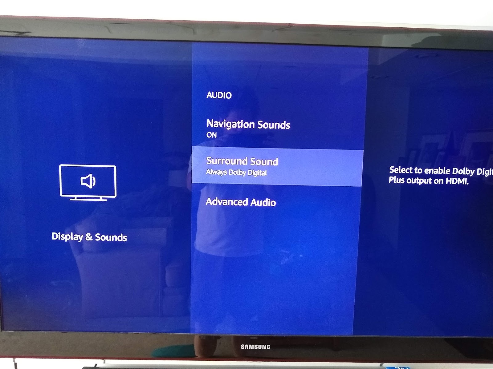
Make sure you tell the Fire TV Cube to always use Dolby Digital, you'll find this in the settings for the Fire TV Cube as below:

Configure Fire TV Cube to always output Dolby Digital
I've noticed that *some* providers don't give you the surround until you turn it on explicitly.  moviesanywhere.com is one of those providers.  So, keep an eye on your Sonos phone app to see what the Playbar is receiving:

The "About My Sonos System" dialog on my Android phone, indicating what type of signal the Playbar is receiving

My new setup looks like this:
The new setup uses the J-Tech HDMI switch to strip Dolby Digital signals from HDMI inputs and pass them to the Playbar via its own optical digital output

The J-Tech HDMI switcher in service
The only remaining problem with this setup is the internal TV tuner.  If I want to watch OTA TV, I have to connect the optical output from the TV directly to the Playbar.  This might be solved by adding a separate TV tuner device, like this one (that also provides recording capability).  There are also several devices that will provide one or two TV tuners, and make that TV signal available for streaming by your laptop, TV, phone, etc.  The Amazon Fire TV Recast is one such device.

I hope this helps you with your Sonos Playbar setup.


Sunday, January 7, 2018

How to install KICAD libraries in Ubuntu Linux (or Mint)

After installing KiCAD from PPA on my Linux machine, I had no libraries installed.  Here's he method used to install the libraries from github.  I did the following with KiCAD 4.0.7.

1. Use github to pull the kicad libraries:
~/Projects $ git clone https://github.com/KiCad/kicad-library.git

2. Switch to kicad-library and do: 
~/Projects/kicad-library $ cmake .


3. After cmake creates the makefile, run:
sudo make install


4. Watch the output of the above command.  You should find that stuff gets installed into
/usr/local/share/kicad

5. Restart KiCAD and adjust paths under
Preferences->Configure Paths


6. Restart KiCAD again.

You may *still* see this window in Linux:


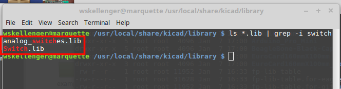
This is because, as near as I can tell, these are old library names, and in Linux, they should be case-sensitive.  For example, the above error shows that "switches" is not found, but:


Notice there is a "analog_switches.lib" as well as a "Switch.lib".  From the Component libraries preferences, you can remove *all* of the default component library files:


Now click "Add" and select *all* of the *.lib files from /usr/local/share/kicad/library.


Sunday, April 9, 2017

Updated: Datalogging with Google Sheets in 2017

In 2011 I posted an article about datalogging with Google Sheets.  I just got a comment asking if the info was still valid.  Google Sheets has changed a lot in the last few years, so here is an updated tutorial for 2017.

1.  Go to Google Sheets
2.  Create a blank sheet


3.  Create a form


4.  Create a single question of type "short answer"


5.  When you've created the question "What is the temperature" with type "short answer" as above, close the tab in your browser.

6.  Reopen the spreadsheet from step 3.  You should now see:

If you don't see this, close and re-open the spreadsheet from Google Sheets.

7.  Google now stores all of your forms at Google Forms.  Go there and you should see the form you created in step 4.

8.  Click the SEND button


9.  Click the link icon to get a link to your form


10.  Copy/paste the link into your browser.  I'm using Chrome.

11.  After the form opens in your browser, hit ctrl+shift+i to open the developer console.

12.  Click the "Network" tab, and also click the option "Preserve Log".  Your screen should look like this:


13.  Type an answer in your form and hit submit.


14.  A bunch of stuff will appear in the Network tab.  This is the browser magic that happens in the background.  Scroll to the top and find the "formResponse" with type "document", like this:


15.  Click this line, and you'll be able to see more information.  The cool stuff will be the "general" tab and the "form data" tab as shown here:


16.  Now we have enough information to assemble a URL that simulates a form response.  The format is:

  • Your request URL: (copy/paste from the information above)
  • Add a question mark to the end of the request URL
  • Add entry.xxxxxx= after the question mark (copy from the "Form Data" section)
  • Paste that entire string into your browser's address bar and hit enter.
Here is an example using my spreadsheet:

https://docs.google.com/forms/d/e/1FAIpQLSe0K7ICSWcMv_-oBO42-irBkkSln4Qu5IxPfPgT-9GQqOyB7w/formResponse?entry.1743242728=11223344


If you copy/paste the above URL into your browser, you will append "11223344" into my example sheet.

Similarly, if you copy/paste this URL into your browser:

https://docs.google.com/forms/d/e/1FAIpQLSe0K7ICSWcMv_-oBO42-irBkkSln4Qu5IxPfPgT-9GQqOyB7w/formResponse?entry.1743242728=999999


999999 will be appended into my example sheet.  I've made the sheet public and you can see the results instantly here.

If you follow the instructions above, you can do the same thing for your own sheets, and use them for datalogging, from IoT devices or really anything that is internet-enabled.

Have fun.

Saturday, April 1, 2017

Martian Notifier Teardown


I bought a Martian Notifier watch new from Amazon for $33.  This seemed to be the perfect 'smart' watch for me, it has only one line of text and has a battery life (for the 'smart' portion) of about five days.  The 'watch' portion uses a quartz movement and separate battery that will give you the time with real hands for about three years.  Although it is now on the market for more than 3 years, the liquidation price was attractive to me.

My Martian Notifier (with aftermarket nylon band)
I like the look of a nylon band (seems military-ish) so I bought this one originally for my Moto 360 (a pile of garbage that I returned after a week).  I still had this band and the 22mm size was a match for the Notifier, so on it goes:

Aftermarket 22mm nylon band on the Notifier

(Thinking about) Hacking the Notifier

I've been wearing the Notifier for a week now, and I like it.  However, as with any tech there are things I wish it did differently.

I can't find any evidence that anyone has tried to hack the Notifier's firmware yet.  So far I've been able to capture a firmware flash of the watch, but I've not tried to reflash it yet.  Martian created a Windows or Mac based Firmware upgrade tool that downloads the firmware and updates the watch.

I've got USB captures of this tool asking the watch for the firmware version as well as the entire upgrade process.

Before bricking my new watch, I wanted to know what kind of hardware was inside it, so I purchased a broken one on eBay for $5.  The broken watch was in perfect shape, so I charged it overnight to be sure it was dead.  The watch showed some signs of life, with the notification LED blinking red (solid red is normal for charging) but the watch never fully booting.  I took the watch apart and found that it had terminal water damage.  It was a good teardown candidate.

Notifier Teardown

Surprisingly, it seems no one has done a public teardown of this watch yet.  I did find this commercially available teardown report but to you have to buy it to read it.

Here's my ten-cent teardown.

Photo album of terrible photos here.

Martian Notifier Watch
  • Watch movement: Miyota 2025 2 hand quartz movement
  • Watch battery: 377 / SR626SW

Martian Notifier Layout

Martian Notifier Connected Device Hardware Details
  • Battery: AE292025P -- marked as containing lead -- LiPoly? 
    • 3.7V (?), 0.44Wh
    • Can't find a hit for the 292025 part number, but 302025 looks very similar.
  • Display: PG-9616TSWD
    • 96x16 OLED
    • I2C interface
    • This one is similar
  • Microprocessor: CSR 8670CG
    • Has a lot of capabilites, including onboard DSP and audio output
    • Not much info about programming this device in the public domain
  • 3-Axis Accelerometer: 263 8451 3EAF
    • Comes from NXP.  Datasheet here.
    • Probably Martian was intending to use this accelerometer for fitness tracking, but maybe due to the hit to battery life decided against it.  The watch software and phone companion app makes no use of this hardware that I can tell.
  • Flash memory: MX25U1635E (3R181 000-X)
    • Macronix serial flash, 1.8V, 16 MBit
    • Not clear what the purpose of this flash storage is.  The 8670 micro has 16 Mbit of flash onboard already.
    • Guess: this flash storage is possibly used for holding an updated version of the device firmware, rather than reprogramming the flash storage on the micro?
If I get any farther hacking the watch, I'll have another post about it.

Sunday, February 5, 2017

Moto G4 Root from Linux

Here are the steps I followed to root my Moto G4.  There were some guides on xda that involved reflashing boot.img.  While it seems many have done this with success, flashing the boot.img is not something I like doing and I try to avoid it if at all possible.  The below method will will modify the boot image, but the SuperSU installation script does it for you.  In my opinion this is still risky but perhaps less risky than flashing a boot.img that you found on the internet.

I performed all of the below steps from my Linux machine; there is no need to use Windows.

Unlocking the bootloader is the same as performing a system reset; you will lose all of your data, so make a backup first.

If you brick your phone following these steps, well, that's on you.

Preliminary Steps

  1. Enable developer options on the phone
  2. Inside developer options, enable "OEM Unlocking"
  3. Enable "USB debugging"
  4. On the computer: have the Android SDK installed (at least adb and fastboot utilities)
  5. Back up important data/pictures/etc from the phone.

Unlock Bootloader

Reboot the phone into the bootloader:


wskellenger@marquette ~ $ adb reboot bootloader

See if the device is visible:

wskellenger@marquette ~ $ fastboot devices

no permissions (verify udev rules); see [http://developer.android.com/tools/device.html] fastboot
For me, it was visible but with no permissions.  Try it with root:
wskellenger@marquette ~ $ sudo $(which fastboot) devices

ZY223R9KC9 fastboot

Obtain the unlock (unique to your phone):

wskellenger@marquette ~ $ sudo $(which fastboot) oem get_unlock_data

(bootloader) slot-count: not found
(bootloader) slot-suffixes: not found
...
(bootloader) Unlock data:
(bootloader) 3A45210437945222#
(bootloader) 5A5932323352394B4339004D6F746F2047200000#
(bootloader) 5342C312F53218107391149534B38F6928DBBD07#
(bootloader) C6506801000000000000000000000000
OKAY [  0.103s]
finished. total time: 0.103s

Format the unlock seed:

Copy the output lines and paste them into vim.  Then do:


(note the search/replace command at the bottom)
:%s/(bootloader) //gc

Accept all replacements.  You now have this:


Place your cursor on the first line and type "4gJ" to join all of the lines without spaces:


Get your unlock key from Motorola:

Go here, and paste the string you created above from vim into Motorola's webpage:


A friendly/pleasant (really!) email will arrive with the unlock code:


UNLOCKING THE BOOTLOADER IS THE SAME AS PERFORMING A FACTORY RESET.

YOU *WILL* LOSE DATA.  SEE HERE.


If you are comfortable with this, unlock it with:

sudo $(which fastboot) oem unlock [your key here]

You have to run the command twice:


Install TWRP

Get what you need

This post from xda-developers describes what you need.

Download the TWRP image

The TWRP image is available here.

Verify image integrity

You should confirm integrity of the download by also downloading the md5 file, and checking that the first few/last few characters of each md5 agree:
wskellenger@marquette ~/Downloads $ md5sum twrp-3.0.2-0-athene.img
1c3ed996a8e978c05bfd25da47eb1e47  twrp-3.0.2-0-athene.img

wskellenger@marquette ~/Downloads $ cat twrp-3.0.2-0-athene.img.md5
1c3ed996a8e978c05bfd25da47eb1e47  twrp-3.0.2-0-athene.img

Use mfastboot to flash the recovery image

mfastboot is a motorola specific fastboot utility.  You can find it on xda-developers.com.  Use it to flash the recovery image.  Here I'm also updating the logo so I don't have the annoying bright white warning about the unlocked bootloader.


Reboot into TWRP recovery

While you are still in the bootloader, you can use the up/down arrows to highlight "recovery" and the press the power button to go into recovery.

When you see TWRP recovery appear, great!  The updated recovery works.  You can reboot the system and set up your Google account, restore your backups, etc.  Note: you aren't rooted yet.

Install SuperSU

Thanks to this post on XDA.

From the phone's browser, download the SuperSU zip from here:
http://download.chainfire.eu/supersu-stable

Shut the phone down, and reboot into TWRP recovery.  Go into the terminal by selecting Advanced-->Terminal.

Inside the terminal, type the following (exactly as written, obeying all spaces, etc.) and press enter:
echo SYSTEMLESS=true>>/data/.supersu

In TWRP, exit the terminal.  Press the home button.  

Install the SuperSU zip from your phone's download directory.  The exact version I used:
SR3-SuperSU-v2.79-SR3-20170114223742.zip

Reboot the phone.  

It may reboot itself once after this.  When the phone boots, SuperSU will be in the app list.  


Saturday, December 10, 2016

Don't Be a Cotton Headed Ninnymuggins T-Shirt Iron-On Transfer Design


This line from Will Ferrell in the movie Elf has turned into a bunch of t-shirts.  


When my wife wanted one for a Christmas party we were going to, I decided to duplicate one of the designs by hand in Inkscape, which would then allow me to resize it as large as I wanted without distortion.  I already had some iron-on transfer paper in stock.


Here's the inkscape svg file if you want to iron-on this design to your own t-shirt.

Sunday, July 10, 2016

"Obsolete" Yamaha/Mando Marine Alternator Drop-In Replacement for YSC-10140-01-AC

The short version:

Smoked 51A Mando alternator
Yamaha part number YSC-10140-01-AC
Mando part number A000B0511
  • 25 year old alternator with Yamaha part number YSC-10140-01-AC failed
  • An exact replacement is no longer available
  • This one worked as a replacement
  • Do your own research, don't blame me if it doesn't work for you.


The long version:

My dad has a 1993-ish Sylvan Barritz that he purchased new.  The boat gets used only about 3-4 months out of the year, and pretty infrequently at that.  Still, our family has gotten almost 25 years of enjoyment out of this boat with relatively little trouble.


Last year (2015), he had a little bit of trouble with a 60A breaker between the alternator and the battery that kept tripping.  One time it tripped and would not reset while he was out in the middle of the bay with some friends.  The solution at that time was to simply eliminate the breaker, which would let them at least get back to shore.  The thinking was that maybe the breaker was flaky after all of the time the nearly 25 year-old boat spends sitting, from fall through spring.

Still enjoying the heck out of this 90s Sylvan Barritz that my dad bought new
(2012 Photo)
This year (2016) he had the entire boat reupholstered, and it looks like new.  He was excited to get it on the water, and my kids were excited to go swimming, so for the first voyage this year he and I decided to take it out and iron out any kinks from sitting all winter.  Launching was fine, and after a little cranking she started right up.  We headed east from Gladstone across Little Bay de Noc for our shakedown run.  The boat was running well and we got her right on plane.  Things were looking fine until about half way across the bay the engine suddenly died and smoke started pouring out from under the engine cover.

Some quick investigation and we found that the 'bush fix' of eliminating the 60A breaker was thankfully not done in a serious or long term way.  The two 8 gauge wires that were meant to be connected and protected by the 60A circuit breaker were smoking and mostly melted, and the small sheet metal screw that was intended last year as a stop gap measure to hold them together had thankfully let go, preventing a major fire.

Photo:
The boat has made hundreds of trips across Little Bay de Noc.
Often my dad will take multiple trips carting family and friends over
to a nice swimming area on the east side of the bay.
(2013 Photo)
Obviously, we had a dead short on our hands somewhere.  Nothing else in the boat would draw as much current as an oven, which given the smoke and melted wires, is what we had.  We waited a bit for the wires to cool and then tried to touch them together where they had formerly been held with a screw.  This produced a violent arc, as the two red wires were now somehow one red, one black.

Tracing the heavy wire around the back of the engine we discovered that the wire attached to the back of the alternator was somewhat melted-looking.  This indicated that somehow internally the alternator had failed, causing a dead short to ground.  It was now clear that the 60A breaker tripping in 2015 was a warning shot; the alternator was telling us that it had provided almost 25 years of service and could do no more.

Luckily my dad had a few tools on board, so without too much trouble we pulled the main wire from the back of the alternator and again tried to touch the red wires together.  This time, no arc.  This confirmed the suspicion that the alternator was the cause of the short, and without the 60A breaker in the circuit the wires had no choice but to become toaster elements.

We were able to start the boat up and run it back to shore without the alternator, knowing that the battery would power the starter and ignition system, but without the alternator we would only be okay as long as the battery would stay about 9-10V or so.

After landing the boat we pulled her home and I pulled out the old alternator.  We found it had a lot of missing cooling fins and the unit would rattle when shaken.

Sidebar:  Let me briefly describe the engine in this boat.  It is a GM-derived 3.0L 4 cylinder.  Someone should write up the entire history of this thing, but from what I've read, it appears to be developed for marine use by Mercury Marine (however some sources say Yamaha developed it).  Some people say it derived from the 2.5L iron duke, others say no, it was an older engine.  Nevertheless this engine seems to have a home in lots of boats.

The stern drive is another story.  This particular one is from Yamaha, and from what I can tell it is quite rare in the US.  A search of marine forums for "Yamaha 3.0L stern drive" and you will find posts where people are in search of parts, or they bought such a boat as a 'project boat' and quickly found they can't find parts for the stern drive.

Still, I thought finding an alternator would not be a big deal for this thing.  Another side note: I quickly discovered that you *must* use a marine alternator replacement, as they are fitted with spark arresting devices to avoid igniting the fumes in the engine compartment.  Do NOT attempt to replace this alternator with an automotive unit!

A first search yielded a guy trying to sell this exact alternator, used, for $300:


Absolutely no way would I purchase a 25 year old alternator for $300.  I blurred out the seller name above as I don't want this to reflect badly on him; if he can get $300 for it, more power to him.  But having the exact replacement isn't necessary.  If I can get a 60A unit or a 40A unit it should work fine.  (Even a 90A unit would be fine if I knew that the wires would handle the current and the existing circuit breaker were upgraded.)

You can search around and find out more panic-inducing results like this one from boats.net, indicating that it is NOT AVAILABLE and OBSOLETE even thought it used in a lot of different marine engines:

$301 new, but obsolete and not available

Finally I hit on DB Electrical and their AMN0016, which is also available at their Amazon Store.


Specs are nearly the same.  The stock alternator was 51A, this one is listed as 55A.  It is marine-grade.  It has a one year warranty.


The only difference I can find, physically, is that this unit has a single pulley while the stock unit had a double pulleys, for use in two different mounting applications.  Still, if you need a different pulley offset in your application you can swap out the single pulley for the double that you already have.  So don't scrap the existing one until you have the new one in your hands.

I tried calling DB Electrical to discuss this application before I bought it but their tech support line on July 5th was busy, with > 20 minute wait time, so I decided to just order it.  As long as the housing matched the picture it should work fine.  The bolt that it pivots on is a huge 1/2" grade 8 monster, and that hole diameter and the width of the mounting 'foot' was what I was going to ask about.

Here it is installed.  Note the single pulley that came on it was perfectly aligned.  It is literally a drop-in replacement.

DB Electric AMN0016 installed, replacing the broken YSC-10140-01-AC 


The datasheet that came with it:


I wasn't there for the first trip after installation but my dad reports that it worked flawlessly.  He notes that it isn't charging at idle, but just above idle he is seeing 14V on his voltmeter.  This seems to be confirmed by the datasheet above; there is no current output until about 750 rpm or so.  This might be remedied by swapping on a slightly smaller pulley if you need charging while at idle.  Typically you're not sitting and idling the boat for long so I don't think this is a problem.

Disclaimer:  I post this information in the hopes that it helps someone else.  You are responsible for your own property and you are responsible for doing your own homework and research.  If you are not comfortable with a non-standard replacement, you can have the original unit rebuilt (find a starter/alternator repairman), or you can try your luck with a 25 year old used replacement.